Creating New Families
Files you'll need to complete this Lesson
In this lesson we will use the family editor to add reference planes, dimensions, and parameters. We will test these parameters and define family types. Then we will use the different family types in our model.
Getting Started
Make sure you have the source files downloaded for this exercise. You can get them with the links above.
Add Reference Planes for the Frame Component
- Open Revit file:
Lab05_E3_Creating New Families.rvt - Open the
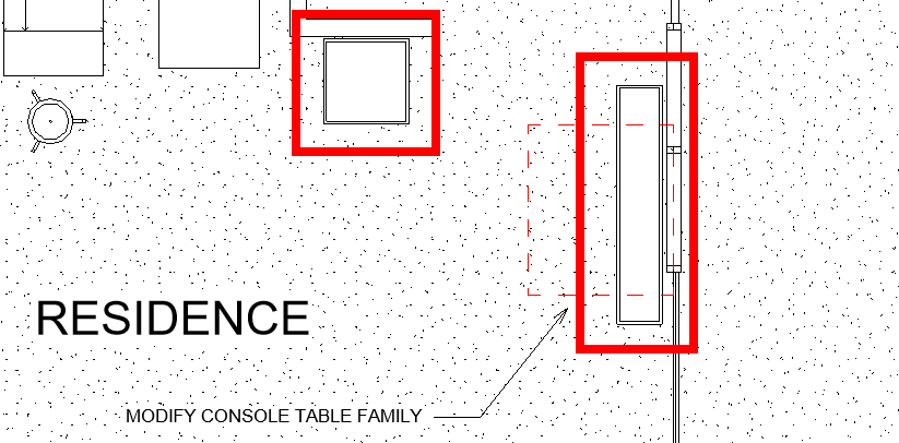
First Floorplan view and zoom in on the residence on the south side of the building. - Select the console table component and click
Edit Familylike in the previous lesson. - Open the
Ref. Levelplan view. - On the Create tab click on the
Reference Planebutton.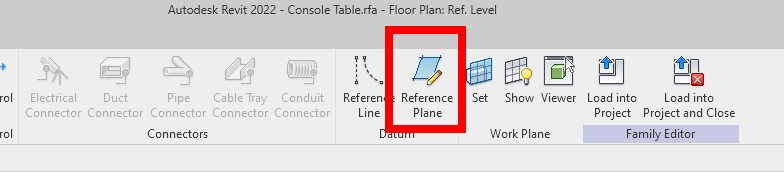
- Click on the
Pick Linestool.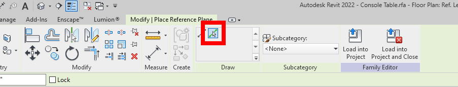
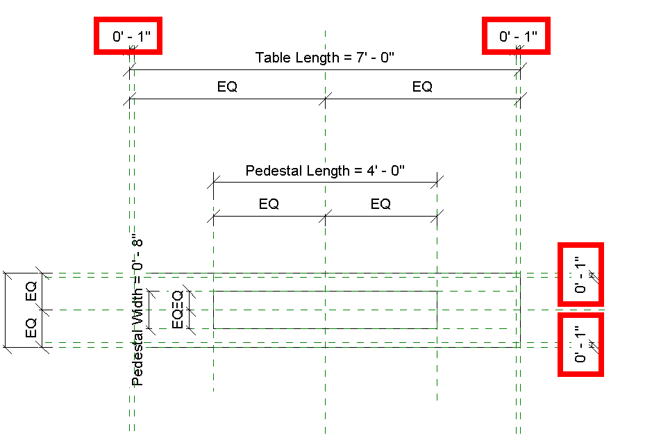
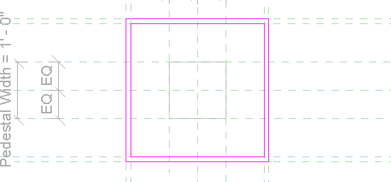
- On the options bar (below the ribbon) set the offset value to
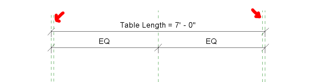
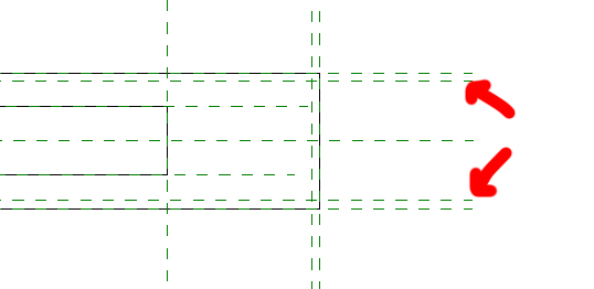
1". - Add a reference plane just inside each of the outer reference planes. (Click near the leftmost and rightmost green dashed lines to add a new reference plane just inside them, and on the topmost and bottom most reference planes to add new ones just inside them too).
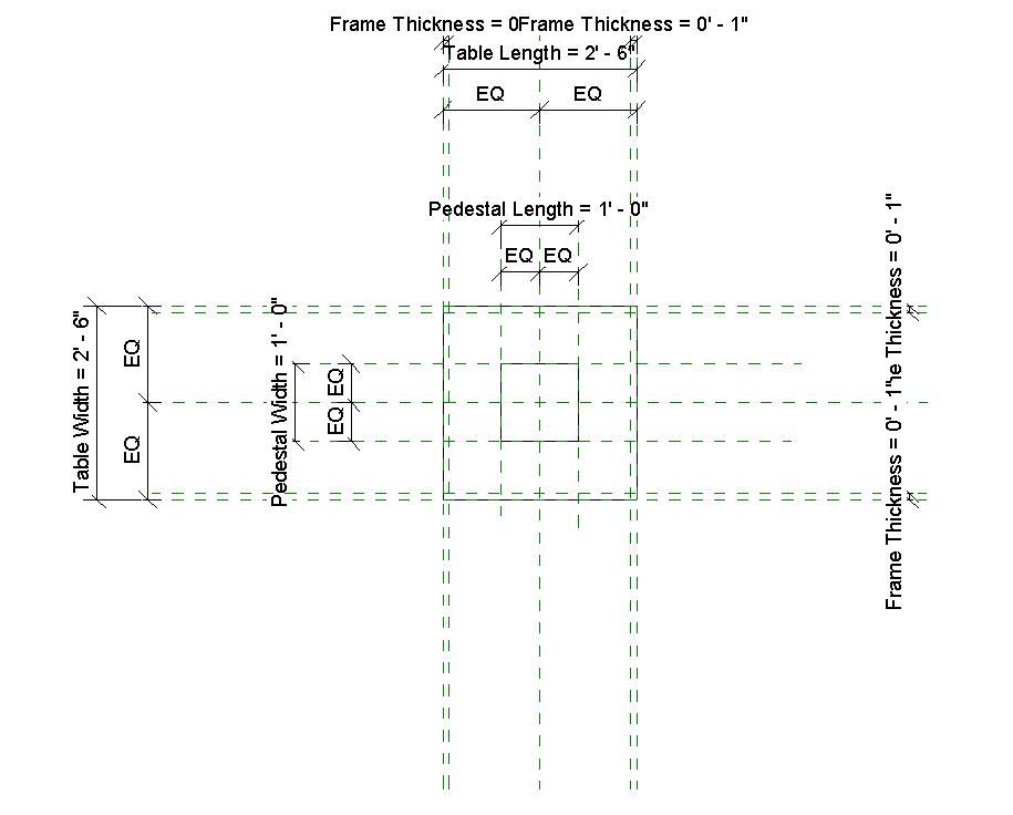
Add Annotation Dimensions between the Reference Planes
- On the Annotate tab click on the
Aligneddimension tool.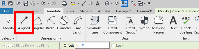
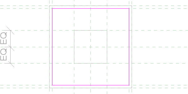
- Create the 4 dimensions showed below:
Make these Annotations Parameters Instead
- Click on one of these new
1"dimensions lines. - On the ribbon click on the
Add Parameterbutton as shown.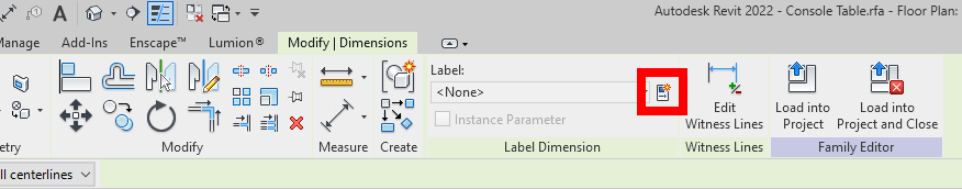
- Name it
Frame Thicknessas shown then clickOK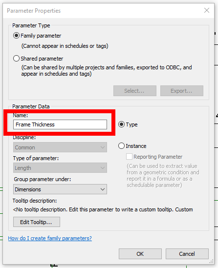
- Select the other 3
1"dimension annotations. - Use the Label dropdown to assign it to the
Frame ThicknessLabel.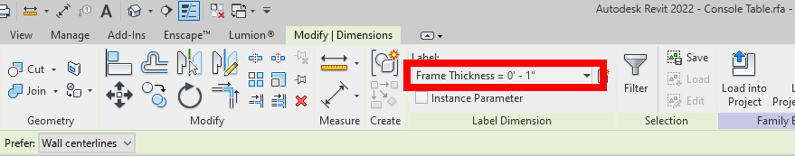
Check Flex Parameters to Move Ref Planes with Model
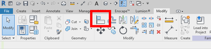
- On the Modify tab click on the
Family Typesbutton.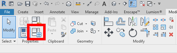
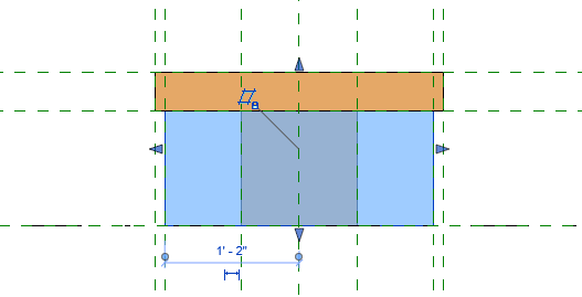
- Use the dropdown to change the type name to
30" L x 30" W x 16" H. Then clickOK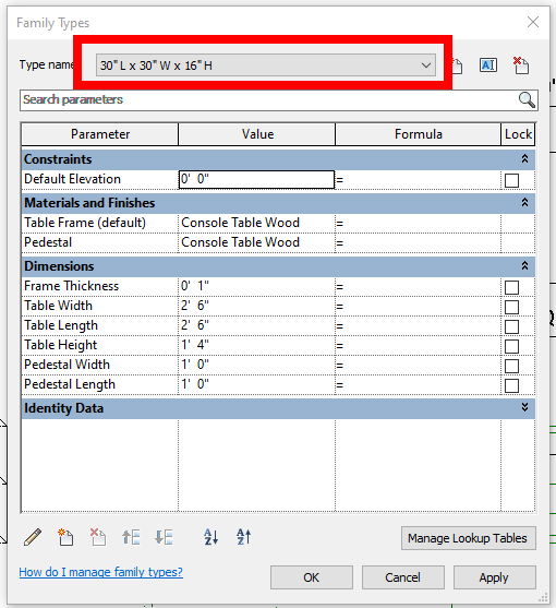
- Confirm that your model moved and looks like our below. If not You might have not added your reference planes and Frame thickness dimensions annotations correctly:
Add Separate Console Table Top Element
- Select the outer extrusion component then
Edit Extrusion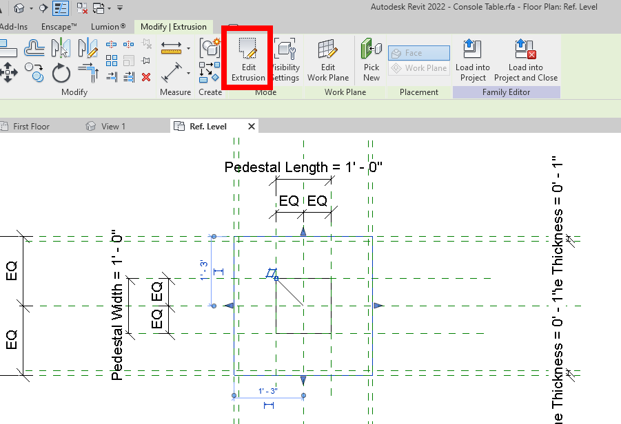
- Use the rectangle draw tool to create another square on the inside of the frame. This will create a hole in the table.
- Confirm the changes.
- Confirm everything is still flexing properly by switching back to the long table version like we did before.
Create the table surface
- Change your model back to the square table.
- Click on the Extrusion tool and use the rectangle draw tool to create a square inside the frame.
- Open the
Frontelevation view. Note that the tabletop is the gray box that is extending all the way to the ground. - Click on the tabletop component.
- In the properties palette click on the little gray rectangle next to the
Extrusion Endconstraint. Set it toTable Height. This will make sure the table top is always at the top. - Add a reference plane 1" below the table top like we have before.
- Create an aligned dimension between the table top and the new reference plane.
- Select this new dimension and create a parameter
Surface Thickness.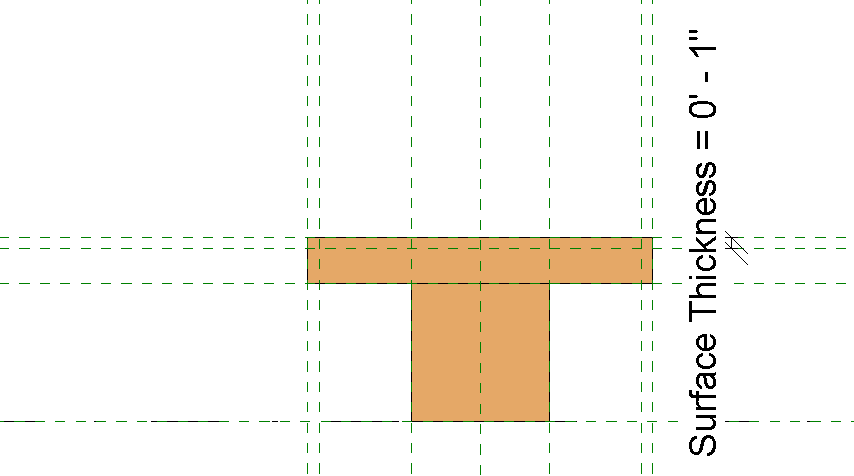
- Select the
4"dimension and create a parameterFrame Height.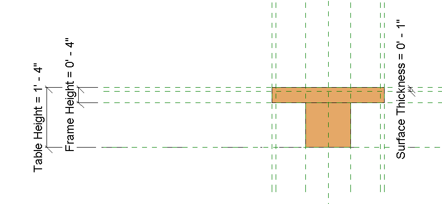
- Click on the Align tool
- Click on the new reference plane for Surface Thickness and then click on the bottom of the tabletop component.
- Click on the lock icon to make it a permanent relationship.
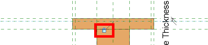
- Repeat this process for the frame height ref plane and the bottom of the frame since the frame not currently locked to the ref plane.
- Confirm everything is moving correctly by switching to the longer version and back again.
Assign Materials
- Open the
{3D}3D view. - Select the table surface component and then on the parameter button (the little gray rectangle) next to the material constraint.
- Click on the
New Parameterbutton. - Name the new parameter
Table Surface. and set it to an instance parameter.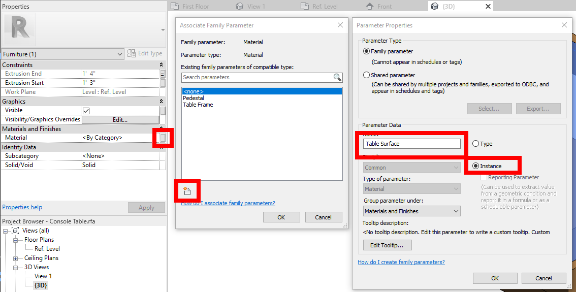
- Click
OKtwice to confirm the new material parameter.
Load and use Family in Project
- Save the family component.
- Load the family into your project. You can overwrite the existing version and it's parameter values.
- Place another instance of the console table next to the wood accent wall.
- Replace the table next to the window with the longer version through the properties palette. See locations below:
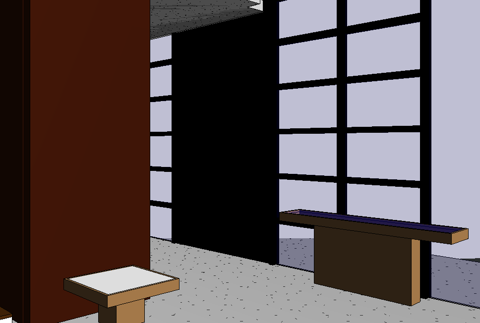
- Open the
Residence3D View. - Change the table surface materials of both tables. Set the smaller table to
White Paneland the larger one toGlass - Confirm yours look the same as ours below:
Save your file
Save your file as Spring2024_3262_firstinitial_lastname_LAB05_EX03.rvt